Design of Intelligent Switching Power Supply Management System for Lithium Battery
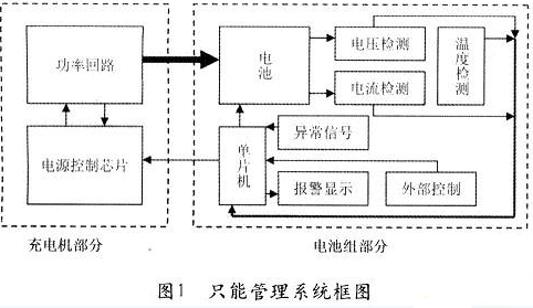
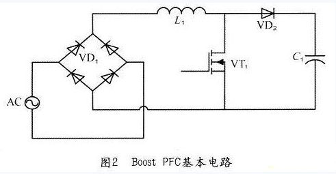
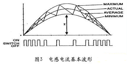
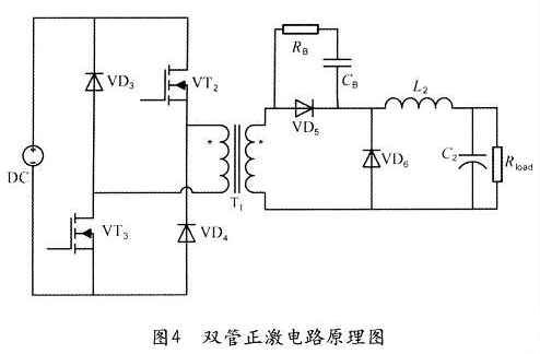
Lithium batteries have the characteristics of small size, large specific energy, long service life and good discharge performance. In just a few years, it has been widely used in notebooks, mobile phones, portable DVDs, VCDs and other devices, and with the development of production technology, there is a trend of further optimization. Lithium batteries have so many advantages, while its manufacturing cost is relatively low, so it is the most promising portable battery in the future. For portable batteries, people want to obtain large-capacity electrical energy while minimizing system weight and increasing battery efficiency and longevity. In addition, due to the cooling conditions of portable devices are generally poor, so the efficiency of the entire power system also put forward higher requirements. The biggest feature of switching power supply is high efficiency. The use of switching power supply, can effectively reduce the power loss of large-capacity battery charging system, thereby greatly reducing the overall system heat. This paper analyzes and designs a lithium-ion / lithium polymer intelligent management system based on switch-mode power supply. Structure of intelligent management system In this paper, the current most widely used constant current and constant voltage charging method, through the use of switching mode power supply to provide battery voltage and current required, and the application of a microcontroller and a series of peripheral circuits to achieve charge and discharge control and battery The protection function The use of SCM and switching power supply can be combined to form an intelligent lithium-ion / lithium polymer battery intelligent management system: the main power circuit of the switching power supply is responsible for converting the electric energy into the form required by the battery charging, and at the same time, the efficiency should be maximized and reduced Small voltage and current ripple; SCM is responsible for controlling the operation of the entire system, including the reference voltage and current value of the charger is given, the charging is completed or the protection state of the charger off, according to the battery voltage, charging current, temperature and other parameters to smart Monitor battery charge status and achieve a range of battery protection features. The entire intelligent management system is divided into two parts: charger and battery pack. Charger mainly includes the main power circuit and part of the power control circuit; and the battery pack includes the battery, detection circuit and microcontroller control circuit. The two parts are connected to each other through an interface, energy is transmitted from the charger to the battery pack, and a part of the control signal controls the charging and discharging circuit of the battery pack to be turned on and off. The other part is sent from the battery pack to the charger to control the start of the charger Turn off and output constant voltage and constant current value. Figure 1 for the entire system block diagram. Figure 1 charger section, the power circuit is the switching power supply, which is responsible for charging the battery, the power control chip to accept from the SCM constant voltage constant current reference control signals, combined with the power loop output voltage and current feedback to achieve the circuit The correct output under different requirements. Part of the battery pack, the microcontroller through the voltage detection, current detection and temperature detection circuit, real-time understanding of the battery in which state to determine whether the battery needs charging, constant current or constant charging voltage, when should end the charging process, the battery Whether there is over-temperature phenomenon and so on. In addition, the microcontroller must also detect abnormal conditions, the battery over-voltage, over-current and temperature is too high and so on, timely protection measures, at the same time alarm signal and display the cause of the alarm. External control can preset constant voltage constant current reference, but also can charge and discharge the process of manual intervention. Circuit design Circuit design, including charger and battery pack two parts. 1) charger design This design of a frequency input, to achieve constant current and constant voltage output AC / DC switching power supply. Charger specific indicators are as follows: Input voltage: 130 ~ 265Vac; Output voltage Uo range: 0 ~ 30Vdc; Output constant current Io range: 0 ~ 10A; Output voltage ripple △ Uppm: <100mV. According to the above charger specifications, the maximum output power of the switching power supply reaches POMAX = UOMAX · IOMAX = 30V × 10A = 300W, assuming the circuit efficiency η = 80%, the maximum input power is due to the larger power, we use PFC + DC / DC two-stage mode to increase the power factor, reduce the adverse impact on the power grid. The PFC section implements the PFC effect using the most commonly used Boost circuit in combination with the CCM average current mode. Boost, PFC basic circuit and waveform shown in Figure 2 and Figure 3: As can be seen from the figure, the average value of the inductor current basically follows the change of the sinusoidal input voltage, so that the whole circuit has a good PF effect and a small THD content, reducing the adverse effect of the converter on the power grid. Due to the circuit's maximum output power POMAX = 300W, DC / DC part of the design choice of larger power capacity, control relatively simple two-transistor forward topology (Figure 4). The topology uses two diodes to reset the magnetizing current and the voltage across the two MOSFETs is also clamped at the input voltage so we can choose a switch with a lower withstand voltage and a relatively smaller on-resistance to effectively reduce The conduction loss of the circuit. However, since the magnetizing current must be reduced to zero before the start of the new switching cycle, the duty cycle of the circuit must be limited to less than 0.5 so that the excitation energy is fully fed back to the input before the end of a cycle, avoiding possible transformer biasing Even saturated phenomenon. 2) control circuit design The control circuit of the charger section mainly includes the auxiliary power section for supplying power to the charger control circuit and the power control chip section (including the control of the PFC and the DC / DC section) of the main power circuit. Besides the constant current reference signal, constant voltage Reference signal and circuit protection signal from the battery pack part of the microcontroller sent to the charger control circuit, the rest
MSG is a professional manufacturer of a
complete line of mail box and other sheet metal fabricated products. We could
produce heavy duty mailboxes with post, planter base, offering variety of
styles, colors & textures. Custom designs of mail boxes are available as
well.
Mail box made of metal material is very
durable and rust resistant. The most common material used to build a mail box
includes steel, stainless steel, zinc-plated sheets, aluminum alloy etc. And
the material surface treatment method includes power coated, anodizing, sand
blasting, zinc plating etc.
Mail Box,Wall Mount Mailbox,External Post Box,Post Mount Mail Box Huiye Hardware & Electrical Equipment Company Ltd. , https://www.huiyehardware.com


