Application of Force Control Software Combined with Internet of Things in Pollution Source Online Monitoring System
The three control modes: one is all the operation control is completed by computer, computer engraving machine at work in the work of the state, unable to carry out other typesetting work, waste may be caused by the misoperation of the computer; two is the use of single-chip control, the engraving machine can work at the same time the layout, but not closed the computer, the computer can reduce the errors caused by the waste, there is only one spindle
X Working Area
1300mm
Y Working Area
2500mm
Z Working Area
200mm
Traveling Positioning Accuracy
±0.05mm
Repositioning Positioning Accuracy
±0.05mm
Table Surface
T-Slot
X,Y ,Z Structure
XY gear wheel, Z ball screw
Max. Power Consumption(Without spindle)
1.84KW
Max. Rapid Travel Rate
25000mm/min
Max. Working Speed
15000mm/min
Spindle Power Motor
3.0KW
Spindle Speed
0-24000r/min
Drive Motor
Stepper
Driver
860,450A
Command
G-code*.u00*.mmg*.plt
Working voltage
AC220V/50Hz
Control System
Copy of NC Studio
Original of NC Studio: The price will add US$500.00
DSP Hand Set: The price will add US$285.00
Guide rail
20 Square rail (TAIWAN BRAND:TBI)
Control cabinet
Independent cabinet
N.W./G.W.
900/1100KGS
Packing Size
3200*2100*1800mm
Single Head Woodworking Machine Single Head Woodworking Machine,Wood Cnc Lathe Machine,Cnc Wood Milling Machine,Wood Cnc Machine JINAN HT MACHINERY CO.,LTD , http://www.jncncrouter.com
2. Introduction to Internet of Things Technology “Internet of Things†is based on the Internet of computers and uses technologies such as radio frequency identification, wireless data communication, and computers to construct a physical Internet that covers everything in the world.
The core and foundation of "Internet of Things technology" is still "Internet technology". It is a kind of network technology that extends and expands on the basis of Internet technology; its user end extends and expands to any item and item for information exchange and communication. Therefore, the definition of the Internet of Things technology is: through information-sensing devices such as radio frequency identification (RFID), infrared sensors, global positioning systems, laser scanners, etc., according to the agreed protocol, any item is connected to the Internet for information exchange and Communication, to achieve intelligent identification, positioning, tracking, monitoring and management of a network technology called the Internet of things technology, force control solution 3.1 system topology diagram system consists of lower acquisition equipment and upper force control eForceConSCADA software, the system uses B /S structure, authorized users can check the system data and observe the operating status in any place where they can log on to the network. 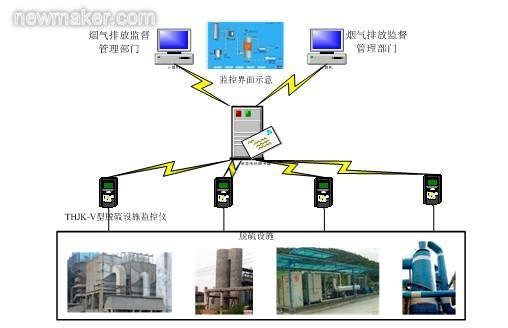
Due to the relatively remote geographical location of some environmental protection testing equipment, the use of network cabling for data transmission is difficult and maintenance is inconvenient. In order to reduce the cost of wiring and the maintenance cost of data transmission lines in the future, this solution adopts the GPRS/CDMA wireless transmission method for the characteristics of the Internet of Things (IoT) devices. Through the force-controlled eForceConSCADA software, the wireless communication module CommBridge, the remote environmental protection data is processed in a data-concurrent manner. Acquisition of environmental monitoring equipment for control and deployment management.
3.2 System Solution Implementation Force Control eForceConSCADA Software In addition to common monitoring functions, remote management has initially achieved the following:
★ Force Control Engineering Remote Deployment and Monitoring Through the deployment of servers, multiple force control can be implemented to monitor the remote deployment of configuration software projects and diagnose the status of product processes.
Force Control eForceCon® series software supports remote deployment, can modify parameters online, is suitable for multi-person collaboration development, builds typical distributed applications, and can simultaneously build multiple application modes such as historical stations, event servers, and alarm servers.
eForceCon is specifically equipped with remote deployment - server and remote deployment - client tools. 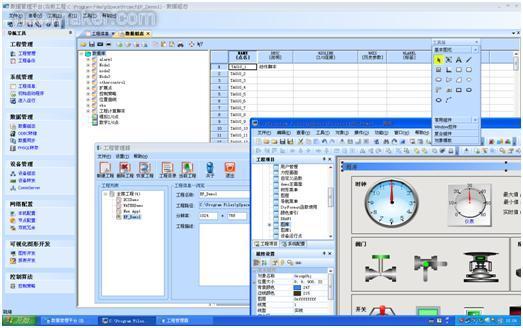
★ Monitoring equipment remote online management and maintenance force control software supports remote online equipment addition and management. The data model, control equipment, and HMI monitoring form a template. The actual objects can be added, managed, and maintained remotely to facilitate the later management of such projects. Through the eForceCon platform, it can realize the collection and upload of field equipment operation data, variable monitoring and parameter setting, and at the same time provide database storage to save the historical data of field equipment operation. The management personnel can browse the operating status data and historical data of the field equipment through the web page, and form a variety of analysis reports through analysis. In addition, the platform also supports running data in the form of specified storage to provide monitoring and analysis workstations for data analysis and processing at the monitoring center. It can simultaneously implement unified access and management of thousands of TCP connections.
★ The model and templated remote device model objects are generally copyable. Therefore, the communication template, real-time data model, and HMI monitoring unit template are quickly integrated from the monitoring point of view to facilitate the maintenance of the product.
★ Product Support Cross-platform applications in the system, from embedded development to scheduling management, force control products to support cross-platform applications, effective combination of large-scale monitoring and management network.
The overall system plan uses three layers (data access layer, business logic layer, and user presentation layer) architecture. The three-tier architecture application program separates the user interface, business rules, and data access. The data access layer encapsulates access to the database. The user interface interacts with the business logic layer and the business logic layer interacts with the data access layer. Through multi-layer separation, good scalability, maintainability, reusability, and security are achieved. The B/SWeb technology application mode runs in LAN and Internet environments, which is easy to deploy and maintain. It is easy to use, has good scalability and flexible adaptability, has strong vitality, and is in line with current and future development trends.
The system has realized the collection and monitoring of key parameters such as operation parameters, equipment operation status, monitoring parameters, and pollution reduction calculation required for waste water and flue gas treatment facilities. The system has collected the water quality indicators and blower currents of the sewage treatment facilities in real time. , Blast volume, operating conditions of aeration equipment, dissolved oxygen concentration, sludge concentration, filter clogging rate and other data; and boiler load, temperature, flow, fan current and blade opening, oxidation fan in the operation of the flue gas desulfurization facility Sealed blower current, pump current, bypass opening, slurry pH, and smoke inlet and outlet process parameters such as sulphur dioxide, soot, and nitrogen oxide concentration eliminated the phenomenon of non-operation of the treatment facility. At the same time, the collected data is stored to a remote dedicated server, and the on-site process is displayed with the human-machine interface restored. The management department can log in, view, and supervise through the Internet and is an effective monitoring system for achieving pollution reduction targets.
Fourth, the main function of the monitoring system user interface: the user enters the correct user name and password will enter their own interface for related operations, smoke management facilities supervision of the overall user interface as shown below: 
The user interface of the wastewater treatment facility supervision is shown below: 
Enterprise List: The user enters his own interface to view all the related information of the enterprises and enterprises within his supervision scope. The list diagram is as follows: 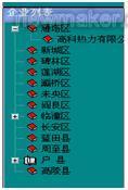
Facilities operating status view: When the user enters his own interface, he can click the relevant company in the enterprise list to view the operating status of each device in the enterprise. The system displays the device operating status as a dynamic graphical human-machine interface to the user with relevant parameters. The interface looks like this: 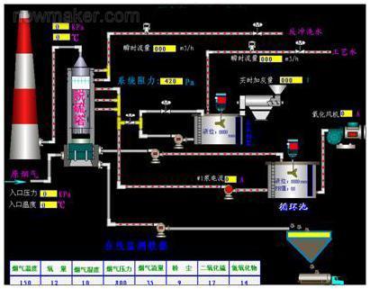
Parameter view: Users can click on the data report graph to view all the data collected by each facility every hour and minute, and have the data of a certain time point or time period inquired of this enterprise, and can also print out the data report. The report graph is as follows: Show: 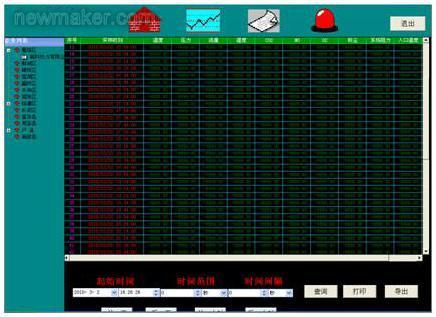
Data graph: The user can see the change curve of one or more data of the company in one day by clicking on the data change curve graph, and has a plurality of data change graphs or a data change in one day of the company. And print graph functions. The graph interface is as follows: 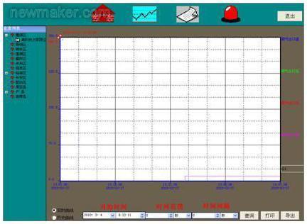
System reminder: When an enterprise facility stops running, the red light in the system blinks. Click on the red light to view the enterprise where the facility is stopped. If the facility operating data is abnormal, the red light will also flash. Click to view the abnormal alarm information. When the facility stops When no data is output, the system will also alarm, indicating missing data. The system reminds the interface as shown below: 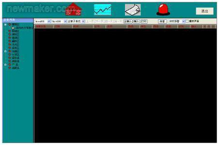
Data printing: data printing and data viewing, query in the same interface, in the data view, query at the same time you can view, query data and charts to print.
Data query: Data query and data view are in the same interface. When a user wants to query a certain data in a time period or a data change curve of a certain day when the user views the enterprise data, you can input the end time and the query item to see what you want. View data and data changes.
System services: System services are mainly used to help users modify their login passwords and provide technical services related company information.
Data modification: This function is mainly for system administrators. The system administrator has the right to modify data if it finds that there is something wrong with the reported data.
Permissions distribution: System administrators have the highest authority to use, and can assign different permissions according to the level of the EPA. For example, the EPA at the district or county level has relevant enterprises in the monitoring districts and counties, and the EPA users can supervise all Business.
V. Summary Using domestic large-scale SCADA software to control eForceCon and IoT technology, real-time monitoring of environmental protection equipment and key operating parameters are performed. At the same time, the collected data is stored to a remote dedicated server and displayed on the human-machine interface. During the technological process, the management department can log in, view and supervise through the Internet, effectively monitor pollution reduction targets, and eliminate the phenomenon of non-operation of the governance facilities.
