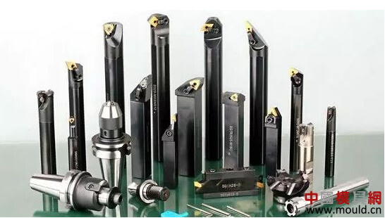
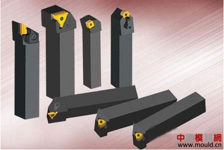
How to grasp the match between the tool and the machine tool?
As a tool that is installed directly or indirectly on a machine tool to complete a workpiece machining task, we must consider two suitability and one matching. This applies to the selected machine tool, to the selected workpiece, to the machining task and to the machine tool. However, this article mainly starts from the matching of the tool and talks about how to grasp the match between the tool and the machine tool. When it comes to the match between the tool and the machine tool, what you may think of first is the matching of the shape and size. Indeed, the matching of form and size is the basis for the correct installation of the tool on the machine. Without this foundation, the tool could not be correctly installed on the machine, so it would not be able to complete any processing tasks. However, this alone is not enough. After the tool is installed on the machine tool, it is necessary to complete a certain processing task. In the course of completing this machining task, it is necessary to ensure the machining accuracy, the need to withstand and transmit cutting forces and cutting torque, the need to complete the acceptance, transfer and export of cutting heat, and the possible disposal of cutting waste (chips and material heads). Even the transmission of workpieces, as well as the modern digital transfer of tool parameters and so on. Some of these tasks, although not common, are also tasks that the tool may undertake. If we can choose the tool and consider the matching of the tool and the machine tool together, it will increase our thinking to solve the processing problem. The assurance of machining accuracy, the transmission of cutting forces and moments, and the provision of channels for cutting fluids are problems that we often encounter after matching the shape and dimensions. For example, in machining centers, we often use a cylindrical shape (usually called a straight shank) as a clamping method. Then for the cylindrical tool holder, in addition to the typical complete cylindrical shape, there are some changes in the cylindrical shape to add some other elements, such as flat-type straight shank (milling cutter is divided into single cut plane and double cut plane according to diameter Two types of drilling, common cutting planes, all known as side pressure type, inclined flat with 2° inclination, straight shank with flat tail (usually used for drills), straight shank with square body (commonly used for taps And reamers) and many other ways. With regard to the coupling of the tool holder with the machine tool, only a cylindrical portion is positioned and clamped. All kinds of pressure angle spring sleeve system, strong chuck system, hydraulic locking system, thermal expansion clamping system, force deformation locking system are all used to lock the cylindrical handle. However, various clamping methods have their own advantages and disadvantages. Take the most common spring sleeve system, the large pressure angle (herein the pressure angle is defined as the angle between the positive pressure of the cone locking and the cylinder axis), that is, a large cone angle represents a shorter locking stroke, It facilitates quick locking and loosening, but the positive pressure that decomposes on the cylindrical surface under the same locking torque is smaller, resulting in a smaller frictional distance and a correspondingly smaller cutting force. It is easy to produce slippage in the tool holder, affecting the smoothness of the machining process and the quality of the machining surface. At the same time, the diameter range of the tool holder that can be clamped by such chucks is relatively large, which helps to reduce the inventory of the spring sleeve and optimize management. The small pressure angle is the opposite. The small pressure angle spring sleeve can hold a small range of shank diameters, and the locking stroke during clamping is long, which is not conducive to fast clamping and loosening, but its clamping accuracy is slightly higher and the clamping force is large. Can withstand greater cutting loads. The hydraulic locking system is an emerging clamping system that utilizes the incompressibility of high-viscosity hydraulic fluid to cause the inner wall of the tool holding cavity to undergo elastic deformation, thereby locking the tool. The high precision of the hydraulic locking system makes it convenient to lock and loosen without special equipment. The locking torque is usually better than the spring sleeve system, but the inner wall can only work within the elastic deformation range. Once outside this range, there will be irreversible plastic deformation of the inner wall, which will cause a permanent failure of the fixture cavity. Therefore, a flat-type shank, especially a full-cut flat shank used for drilling tools, cannot be used in a hydraulic locking system. Cavity pressure, shank not inserted into the bottom of the chamber, etc., are also common causes of damage to the system. The thermal expansion clamping system usually requires special equipment. Such equipment is preferably controlled by heating and cooling in a plurality of predetermined modes. Unprofessional heating equipment (even flame heating) may be used, but often the other parts of the tool holder are affected by the fact that the temperature and heating curve cannot be well controlled, or even the metallurgical structure is changed, and the system quickly fails. In addition, the tool length of the thermal expansion clamping system is difficult to adjust and requires a special auxiliary tool, which adds some trouble to the occasion where multiple tools need to be synchronized. On the other hand, the tool holding method may also determine the possible value of production efficiency. Cylindrical shank and hydraulic pressure, thermal expansion are all suitable for higher speed balanced design, while flat type clamping is a typical non-balanced design, tool manufacturers are included in the ranks not recommended for high-speed cutting. In the case of the shank itself, the center of gravity of the shank portion does not coincide with the center of rotation of the tool when a part of the material is milled (or ground) to form the pressure surface. During the clamping of the tool, the flattened shank is pushed by the locking screw to the side that has been off-center, and the center of gravity of the tool will further deviate from the turning center of the tool on the machine tool, which increases the imbalance of the tool. In addition to the fact that some users randomly attach a screw after the original locking screw is damaged or missing, the length is often careless, and this behavior also adds uncertainty to the balancing performance of the tool. Therefore, the flat type (including bevel flat) is not recommended for use at high speeds. However, the flattened type is a tool shank with a forced drive, which is more reliable than pure cylinders relying entirely on friction drive under high torque. Therefore, it is more appropriate for roughing (general rough torque, but low rotational speed). ERW Steel Pipe,HFW Steel Pipe,ISO3183 STEEL PIPE,HFW Steel Pipe API5L HeBei GuangHao Pipe Fittings Co .,LTD (Cangzhou Sailing Steel Pipe Co., Ltd) , https://www.guanghaofitting.com


Standard
Type of pipe
Class
Grade
C max
Si max
Mn max
P max
S max
V max
Nb max
Ti max
API SPEC 5L
/ISO 3183
WELD
PSL1
L245 B
0.26
-
1.2
-
0.03
0.03
-
-
L290/X42
0.26
-
1.3
-
0.03
0.03
-
-
L320/X46
0.26
-
1.4
-
0.03
0.03
-
-
L360/X52
0.26
-
1.4
-
0.03
0.03
-
-
L390/X56
0.26
-
1.4
-
0.03
0.03
-
-
L415/X60
0.26
-
1.4
-
0.03
0.03
-
-
L450/X65
0.26
-
1.4
-
0.03
0.03
-
-
L485/X70
0.26
-
1.4
-
0.03
0.03
-
-
PSL2
L245M/GR.BM
0.22
0.45
1.2
0.025
0.015
0.05
0.05
0.04
L290M/X42M
0.22
0.45
1.3
0.025
0.015
0.05
0.05
0.04
L320M/X46M
0.22
0.45
1.3
0.025
0.015
0.05
0.05
0.04
L360M/X52M
0.22
0.45
1.4
0.025
0.015
-
-
-
L390M/X56M
0.22
0.45
1.4
0.025
0.015
-
-
-
L415M/X60M
0.12
0.45
1.6
0.025
0.015
-
-
-
L450M/X65M
0.12
0.45
1.6
0.025
0.015
-
-
-
L485M/X70M
0.12
0.45
1.7
0.025
0.015
-
-
-
L555M/X80M
0.12
0.45
1.85
0.025
0.015
-
-
-
Standard
Class
Grade
Yield Strength (MPa)
Tensile Strength (MPa)
Elongation(%)
Y.S/T.S
API SPEC 5L
/ISO 3183
PSL1
L245 B
min
245
415
b
-
L290/X42
min
290
415
b
-
L320/X46
min
320
435
b
-
L360/X52
min
360
460
b
-
L390/X56
min
390
490
b
-
L415/X60
min
415
520
b
-
L450/X65
min
450
535
b
-
L485/X70
min
480
470
b
-
PSL2
L245N/BN
L245M/BM
min
245
415
b
-
max
450
760
b
0.93
L290N/X42N
L290M/X42M
min
290
415
b
-
max
495
760
b
0.93
L320N/X46N
L320M/X46M
min
320
435
b
-
max
525
760
b
0.93
L360N/X52N
L360M/X52M
min
360
460
b
-
max
530
760
b
0.93
L390N/X56N
L390M/X56M
min
390
490
b
-
max
545
760
b
0.93
L415N/X60N
L415M/X60M
min
415
520
b
-
max
565
760
b
0.93
L450M/X65M
min
450
535
b
-
max
600
760
b
0.93
L485M/X70M
min
485
570
b
-
max
635
760
b
0.93
L555M/X80M
min
555
625
b
-
max
705
825
b
0.93
