Investigating the Gas Core-Out Ratio of Gas-Assisted Injection Molding through Advanced CAE Technology
In gas-assisted injection molding (GAIM) process, gas is injected into the mold cavity to core out a network of hollow channels and drive the polymer melt to form a part. Compared to conventional injection molding, GAIM is a breakthrough technology that is able to save plastic materials and shorten the cycle time. However, sometimes GAIM is still limited since the gas is difficult to control and observe during the process. Also, many new design parameters such as gas injection port location and number, the starting gas injection time, and injection pressure and flow rate, often greatly affect the mold development cost. In order to solve the issues above, Moldex3D Gas-Assisted Injection Molding (GAIM) module enables users to visualize the gas penetration behaviors and provides overflow predictions. Users can use the tool to optimize filling parameters, including gas time control, gas enter location and the overflow region and also to predict potential defects such as weld lines, flow marks, shrinkage, or flatness. The simulation also enables visualization of the thickness and core-out ratio distributions. The following case is a thin plate with a semicircular cross section gas channel (Fig. 1). The predicted filling patterns at different polymer injection phase are illustrated in Fig. 2. According to the published experimental data (Ref. 1), the measured gas penetration length is about 15.8 cm. The gas penetration length predicted by Moldex3D is 16.0 cm, which correlates well with the experimental observations on the polymer melt locations. In order to examine the gas penetration in the lateral direction, both the simulation and experiment results of the gas core-out ratio along the gas penetration direction are plotted in Fig. 3. The definition of gas core-out ratio is in Fig. 4. The predicted ratio in the present framework shows the same trend as the experimental value. The gas core-out ratio is observed almost constant during the primary penetration. Thereafter, it decreases with a slope at the secondary penetration and finally becomes zero at the bubble tip. The results proved the Moldex3D can predict both the primary and secondary penetration phenomena precisely in gas-assisted injection molding process. The experimental results are in good agreement with the simulation results. This proves that Moldex3D GAIM is able to model the polymer melt filling and gas penetration in GAIM, and users can easily visualize the skin thickness and core-out ratio distributions through the simulation results. Thus, it enables a better understanding of the melt and gas behaviors to allow more flexibilities in design optimization before actual manufacturing.
U&C Channel steel is a long strip of steel with a groove-shaped cross-section. Its specifications are expressed in millimeters of waist height (h) * leg width (b) * waist thickness (d), such as 120*60*5.5, which means that the channel steel with a waist height of 120 mm and a leg width of 60 mm has a waist thickness of 5.5 mm. mm channel steel, or UPE120 channel steel.
Channel steel has a wide range of uses and can be used in construction, machinery manufacturing, automobile manufacturing, shipbuilding and other fields. In the field of construction, channel steel is often used to make steel structure frames, support frames, beams and columns, etc. In the field of machinery manufacturing, channel steel is often used to make machine tool beds, tracks, conveyor belts, etc. In the field of automobile manufacturing, channel steel is often used to make frame, body and so on. In the field of shipbuilding, channel steel is often used to make hull frames, ship equipment, etc.
Mild steel channel is widely used in civil engineering and construction to support floor joists and to weight bear above window and door gaps where the structural load does not require an I beam.
C Channel Steel,Hat Channel Steel,Galvanised Steel Channel Tianjin Youfa Steel Co., Ltd , https://www.youfametal.com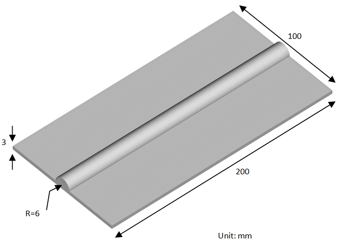 Fig. 1 Geometrical parameters of a thin plate with a gas channel
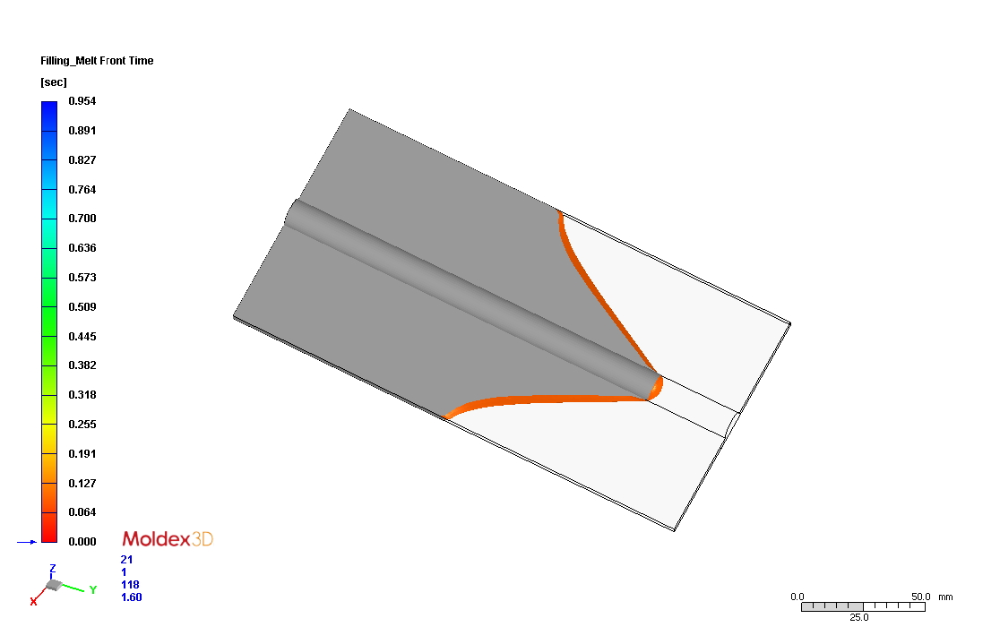 (a)Â Â Â Filling Percentage 75%
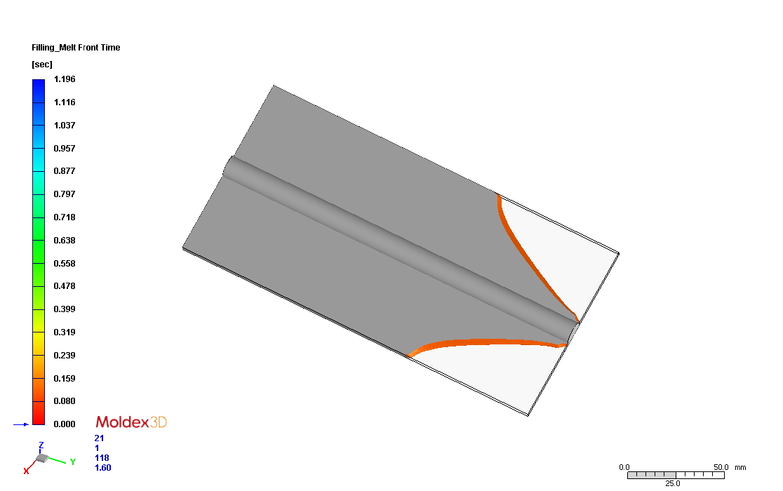 (b)Â Â Â Filling Percentage 94%
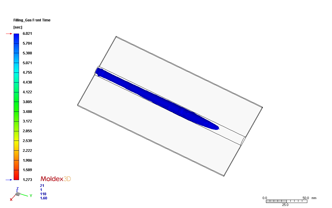 (c)Â Â Â The end of Filling
Fig. 2 The filling patterns of polymer melt and gas fronts of the thin plate.
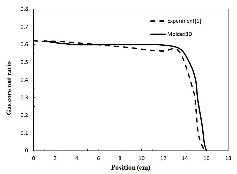 Fig. 3 Distrubtion of Gas-Core out ratio (R-S)/R along the gas penetration direction
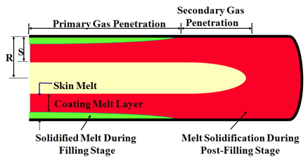 Fig. 4 The definition of the Gas-Core out ratio (R-S)/R
Ref. 1 Â Chen S. C., Cheng N. T., Hu S. Y. Simulation of primary and secondary gas penetration for a gas-assisted injection-molded thin part with gas channel. Journal of Applied Polymer Science 1998; 67: 1553-1564.
